Cameras, Sensors & Others · input layer

The eyes and the senses of the barn.

Cameras read what the cows are doing. Sensors read what the air, the water and the light are doing. Both land in the same control loop — PoE on one side, Modbus on the other.

  • 4 MPPoE cameras, NDAA
  • 4 sensorsClimate to light
  • PoE + ModbusTwo ways in
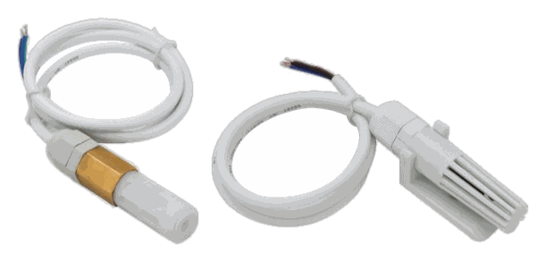
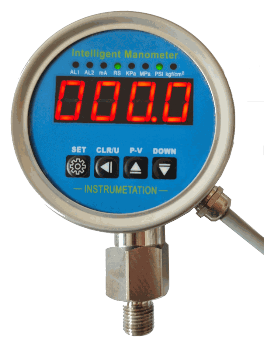
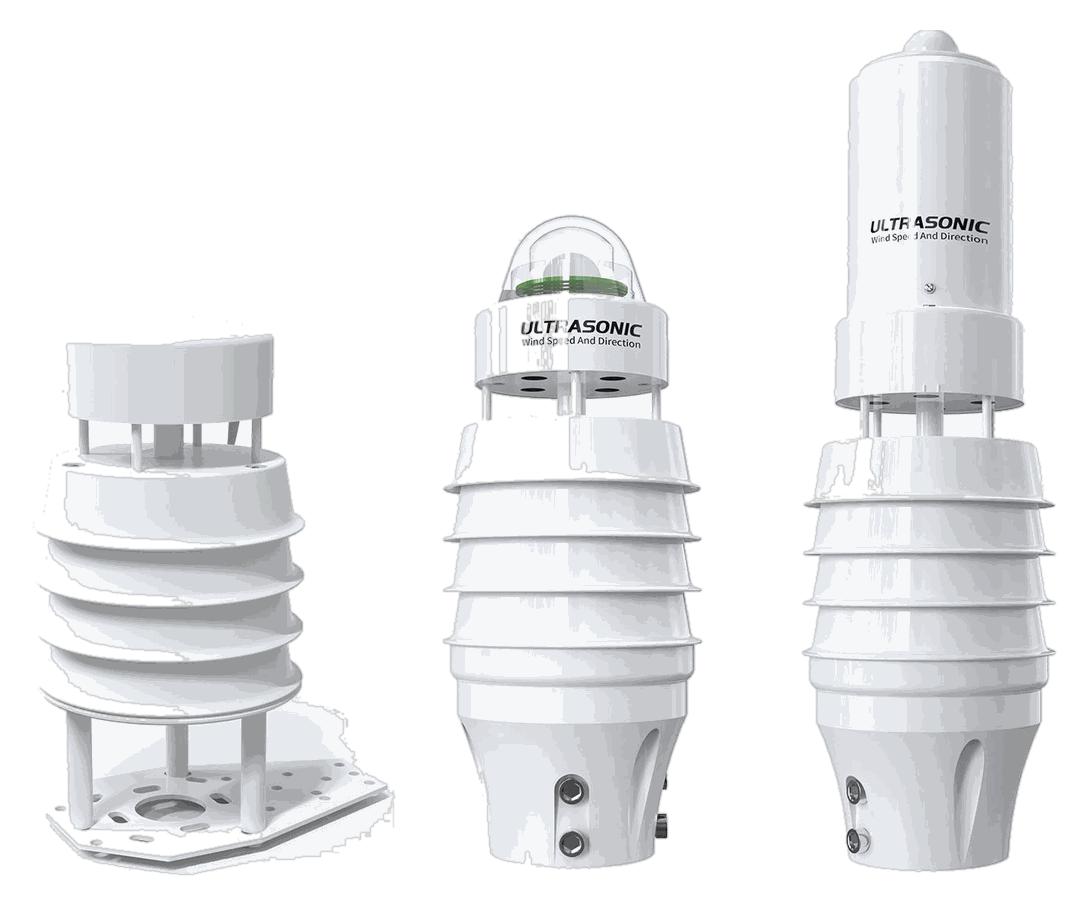
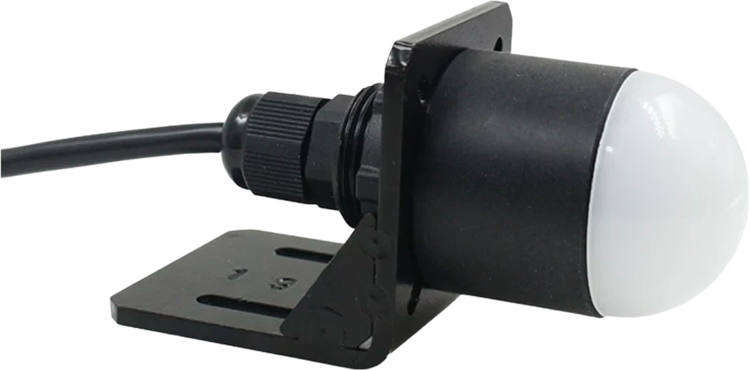
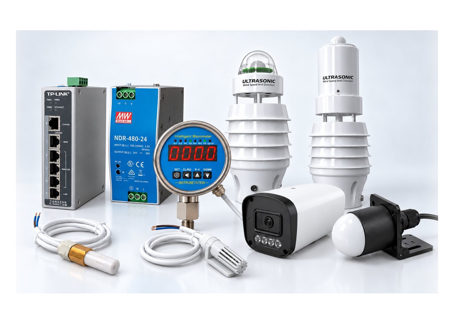
The BARNEYE input family: weather station, intelligent manometer, temperature and humidity probes and a lighting sensor
Weather station, manometer, temperature and humidity probes, lighting sensor.
The line-up

Every input the controller can read

Grouped by what they tell you: what the cows are doing, what the barn is doing, and the network and power that carry both.

Cameras

What the cows are doing, zone by zone.

2 units
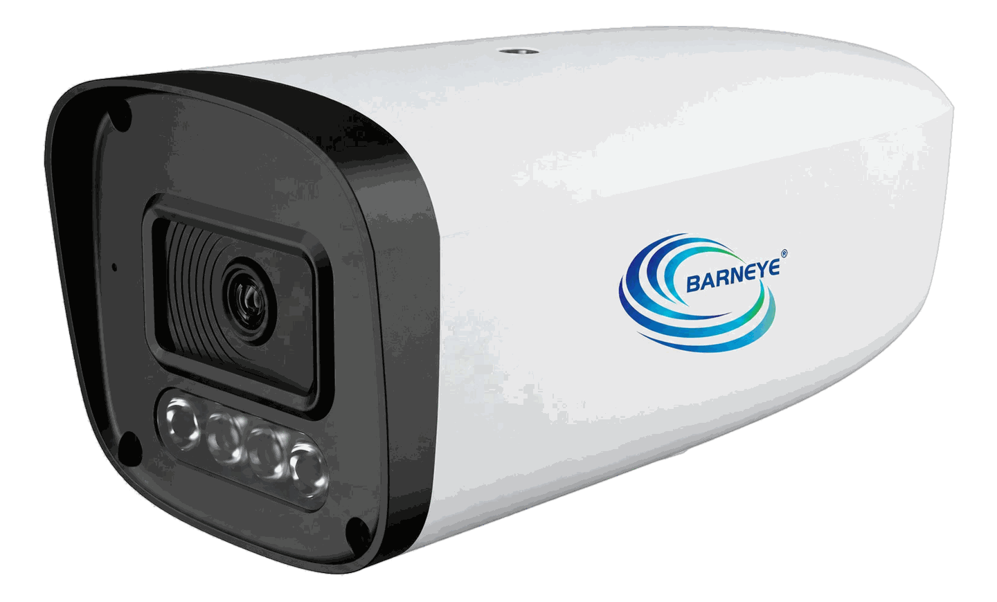
4 MP PoE camera

4 MP PoE camera

Vision input · PoE turret

One 4 MP PoE turret, one part number. Which of the three UNV models ships is decided by the mounting position; the specification does not change — single cable, H.265 / Ultra 265 encoding, NDAA compliant.

Resolution4 MP
PowerPoE
EncodingH.265
ComplianceNDAA

CAM-01-004-001
Vision Counter Box — form factor still to be confirmed

Vision Counter Box

Coming soon

Edge inference · in development

An edge enclosure that counts and times animals through a passage, on site. It is not a controller: the counts go to the Mini-C Plus, and it runs no ventilation or soaking logic of its own.

InferenceOn site
LinkWired to Mini-C
OutputCounts + timing
StatusIn development

TBD

Sensors

What the air, the water and the light are doing.

4 units
Temperature and humidity sensor

Temperature and humidity

Climate node

Barn temperature and humidity in one Modbus node — the baseline reading the ventilation loop starts from.

Range−40…80 °C
Humidity0–100 %
OutputModbus RTU
BodyProbe on cable

SEN-01-001-001

Intelligent manometer

Intelligent manometer

Line pressure

Line pressure in the soaking and fogging circuits, so a blocked nozzle or a leak shows up the moment it happens.

Range0–1.6 MPa
Body304 stainless
Display4-digit LED
OutputModbus

SEN-01-004-001

Intelligent weather station

Intelligent weather station

Outdoor reference

Wind speed and direction, temperature, humidity, noise, PM2.5 and PM10, pressure, illuminance and rainfall in one mast-mounted unit.

ParametersNine in one
Wind0.5–40 m/s
LinkRS-485, 2,000 m
OutputModbus RTU

SEN-01-005-001

Lighting sensor

Lighting sensor

Photoperiod

Illuminance inside the barn, so the photoperiod programme runs closed-loop instead of on a blind schedule.

MeasuresIlluminance
OutputRS-485 · Modbus
MountUnder luminaire
EnclosureBarn-rated

SEN-01-00X-00X

Network & power

How the inputs reach the controller, and what feeds them.

6 SKUs
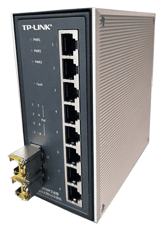
10-port PoE switch

10-port PoE switch

Network · aggregation

Ten-port industrial switch, eight of them PoE, for the camera runs that outgrow the controller's own ports.

Ports10
PoE8 ports
Speed100 / 1000 Mbps
GradeIndustrial

COM-01-002-008

5-port PoE switch

5-port PoE switch

Network · edge

Five ports, four with PoE — the small aggregation point at the far end of the barn.

Ports5
PoE4 ports
Speed100 / 1000 Mbps
GradeIndustrial

COM-01-002-004

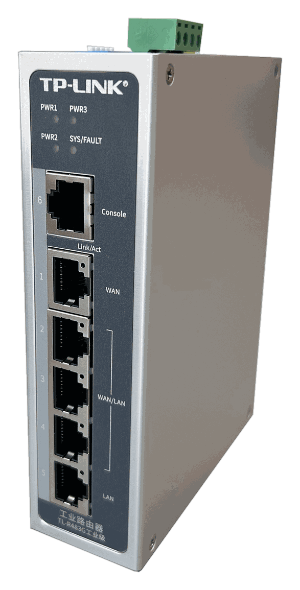
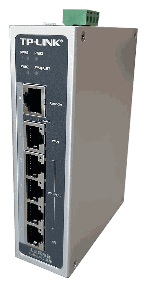
Industrial router

Industrial router

Network · uplink

Multi-WAN gigabit router that puts the barn on the farm network and keeps it there when one link drops.

WANMulti-WAN
SpeedGigabit
MountDIN rail
GradeIndustrial

COM-01-003-004

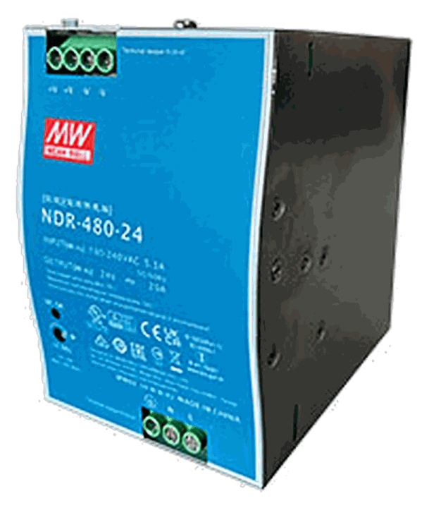
24 V DC power supply

24 V DC power supply

Power · 48 / 240 / 480 W

Power and communication box for soaking controllers: 100–230 V AC in, 24 V DC out, breaker and two 24 V relays included.

Output24 V DC
Rating48 / 240 / 480 W
Input100–230 V AC
IncludedBreaker + 2 relays

Three ratings in this range — contact our engineers and we will confirm the exact configuration for your site.

Controller-side modules live with the controller

CAN, soaker output, inlet, switch, VFD and sensor input are slots inside the Mini-C Plus — not inputs on this page.

  • CANModule
  • VSOModule
  • InletModule
  • SwitchModule
  • VFDModule
  • SensorModule
See the modules
Specification

Compare the range

The points that decide which input a project needs — and what each one can and cannot tell you on its own.

Comparison
Camera4 MP · PoE
Temp & humiditySEN-01-001-001
ManometerSEN-01-004-001
Weather stationSEN-01-005-001
LightingSEN-01-00X-00X
What it gives youZone images for behaviourAir temperature and RHPressure in the soaking lineWind, rain and radiation outsideWhether the lights are on
InterfacePoE Ethernet, H.265 streamModbus RTUModbus RTUModbus RTU, RS-485 to 2,000 mRS-485 · Modbus
PowerPoE — one cable24 V DC24 V DC24 V DC24 V DC
Where it usually goesEave or truss, above the alleyCow level, in a radiation shieldOn the line, after the pumpMast above the ridgeUnder the luminaire
Read byMini-C PlusDB2 · DB9DB7 · TargetSoakMini-C PlusLighting control

Scroll sideways to see every unit.

Network and power

The parts that carry the signal and feed the field.

Comparison
10-port PoE switchCOM-01-002-008
5-port PoE switchCOM-01-002-004
Industrial routerCOM-01-003-004
24 V DC PSUPWR-02-024-240 / -480
What it doesAggregates cameras and controllersExtends one end of the barnLinks the barn to the farm networkFeeds valves, sensors and relays
Capacity10 ports, 8 with PoE5 ports, 4 with PoEMulti-WAN, gigabit48 / 240 / 480 W at 24 V
MountingDIN rail, cabinetDIN rail, cabinetDIN railDIN rail, power box
Paired withCamera runs past the controller's own portsA short run with a few devicesThe whole-site uplinkSoaking controllers and valves
  • Supply. Sensors run on 24 V DC from the controller; confirm the terminal and the current per unit in its datasheet.
  • PoE budget. The controller's own PoE ports are shared across the cameras on them — an external switch is how a run grows past that.
  • Three camera models, one part number. The turrets — IPC3624LE-ADF28(40)K-WP-L, IPC3614SR-ADF28KM-H and IPC3624SR-ADF28KM-WP — are all 4 MP, PoE and NDAA, and share the same P/N; the lens and housing are chosen for the mounting position.
Selection guide

Which input fits your question?

Start from what you need to know, not from the catalogue. Each row points at the unit that answers it.

Is it too hot or too humid where the cows actually lie?

Has a nozzle blocked, or is the line losing pressure?

What is the wind doing outside, above the ridge?

Is the lighting programme actually being kept?

What are the cows doing in this zone?

How many animals passed through this passage?

Camera runs past what the controller can power?

A few devices at the far end of the barn?

Getting the barn onto the farm network?

Powering valves and sensors from one box?

System fit

Where these sit in the system

The inputs start every decision. These are the parts that make it and act on it.

What you can see

  • Cow presence and position
  • Zone activity
  • Animals counted
  • Feed alley traffic

What you can measure

  • Air temperature and humidity
  • Line pressure
  • Wind, rain and radiation
  • Illuminance

Specifying the input layer?

Send us the barn dimensions, the camera positions you have in mind and the sensors you already own. We will come back with a unit list, a mounting plan and a PoE budget.

Request a specification
Coverage planning
Compatibility checked
Datasheets included