
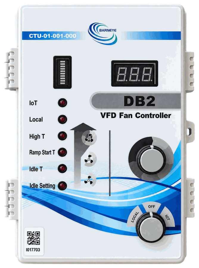
DB2
Shipping nowVFD fan controller
CTU-01-001-000
Temperature in, 0–10 V out. Ten selectable speed levels for one variable-frequency fan, set on the barn wall or from the office.
Output0–10 V
Speed levels10
ModesIoT · Local · Off
EnclosureIP66
The controller decides; the DB Series does. Fans, soakers, inlets and scrapers share one enclosure language, one wiring concept and one status path back to the controller — and the range grows as new terminals are released.
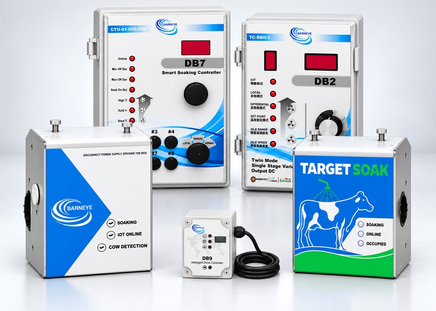
Every unit runs the same control logic and reports back the same way. What changes is what it drives, how it senses and how it is wired.
VFD fan controller
CTU-01-001-000
Temperature in, 0–10 V out. Ten selectable speed levels for one variable-frequency fan, set on the barn wall or from the office.
 ETLFCC
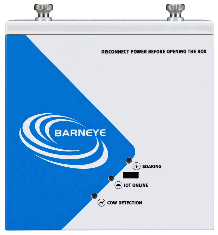
Motion soaker
CTU-01-002-001
Detection, indication and the 24 V valve in one standardised enclosure — the repeating unit along a motion-soaked feedline.
 ETLFCC
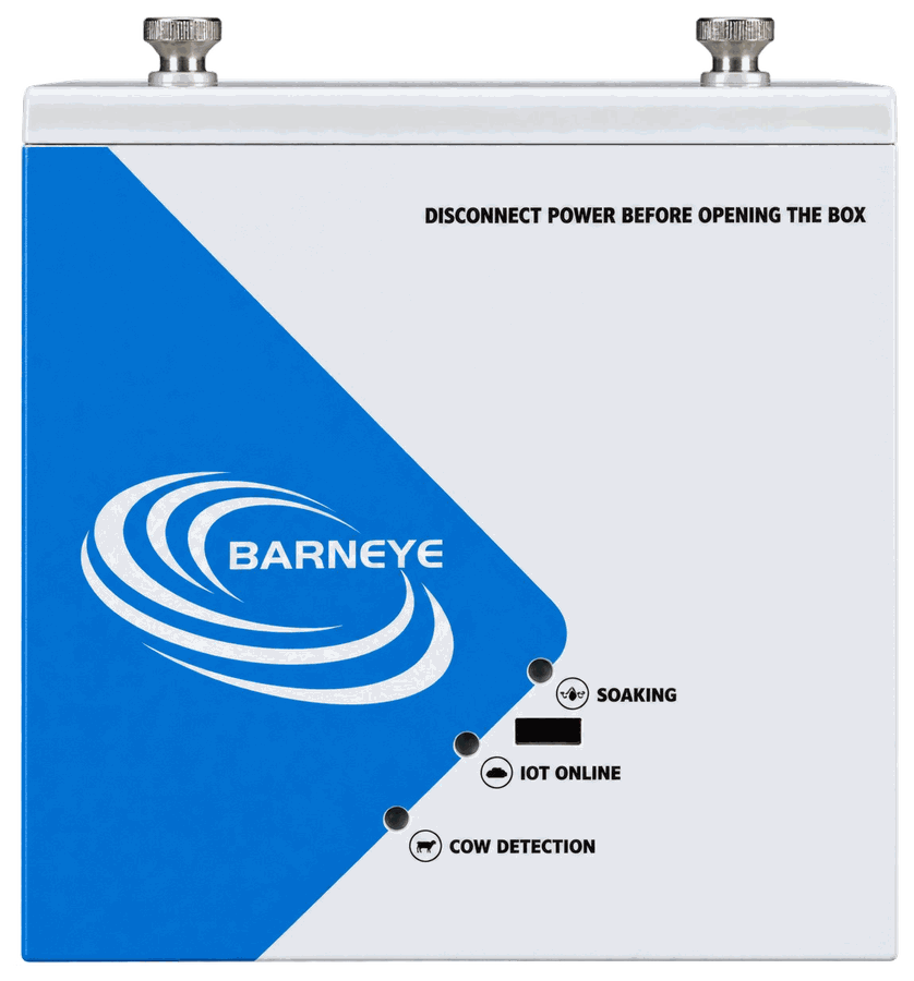
Precision soaker
CTU-01-003-004
Every node runs its own cycle and reports status and operating history back — and takes the Vision Soaking upgrade without rewiring.
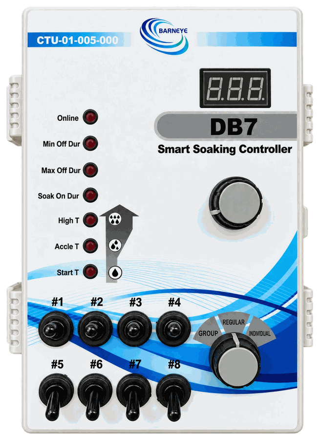
Soaking controller
CTU-01-005-000
Eight switched 24 V circuits in one cabinet: three operating modes, and configuration either at the panel or from an office.
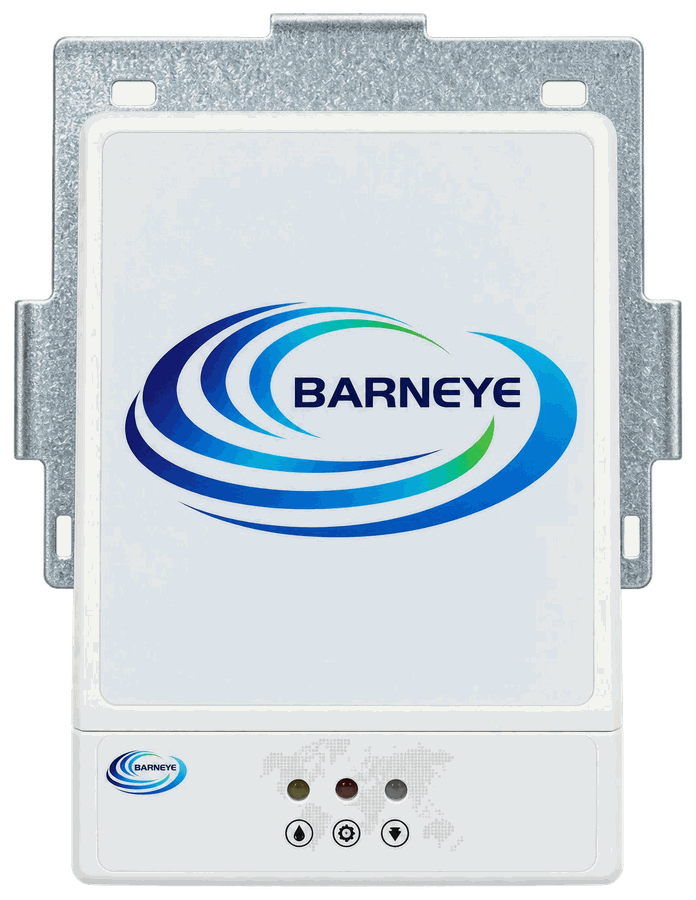
Retrofit motion soaker
CTU-01-006-001
The retrofit route into motion soaking — flexible brackets, an SS316 valve and plug-in wiring onto a feedline that is already there.
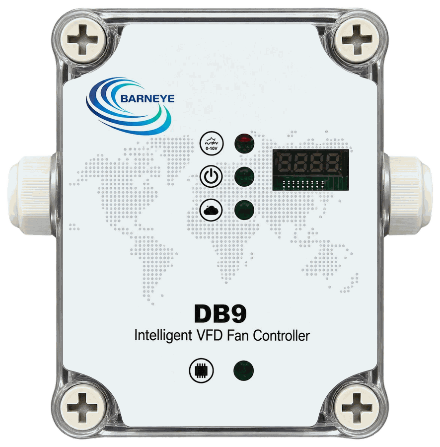
Drive controller
CTU-01-007-000
One interface per fan: 0–10 V command out, live speed, frequency and current back, and local strategy control if the CAN link drops.
Configured per project, so they are quoted rather than carded here. DB10 is the CAN-linked route to the same inlet functions as the INLET module — one control box per inlet group, as with the DB9 — and it is in development, so no specification is published yet. New units join this page, and the comparison above, as they are released.
The points that decide which terminal a project needs — including what each one can and cannot do on its own.
| Comparison | DB2VFD fan controller | DB3Motion soaker | DB5Precision soaker | DB7Soaking controller | DB8Retrofit motion soaker | DB9Drive controller |
|---|---|---|---|---|---|---|
| Controls | One variable-speed fan | One soaking valve | One soaking valve, per node | Up to 8 soaking circuits | One soaking valve | One variable-speed fan |
| How it senses | Barn temperature | Radar motion, 0.75–1.0 m / ±60° | Radar motion, plus cycle data | Programmed zones — regular, group, individual | Radar motion, 2.1 m coverage | Drive data from the VFD |
| Output to the device | 1 × 0–10 V analogue | 24 V DC valve, 3.5 L/min | 24 V DC valve, 3.5 L/min | 8 × 24 V switched, 10 W each | 24 V DC valve, 3.5 L/min | 0–10 V command + switch/enable relay |
| Network and data | Ethernet, RS-485, CAN input | Switched and powered by a DB7 | IoT online — live status and history | Ethernet, RS-485, USB; local or remote | Switched and powered by a DB7 | CAN, plus RS-485/Modbus to the drive |
| Where it mounts | Wall, beside the fan line | Feedline, 1.8–2.0 m high | Feedline, on the existing rail | Wall cabinet, one per zone group | Feedline, 1.7–1.9 m high | Fan group, at the drive |
| Normally specified in | FanPilot Basic | TargetSoak Basic | TargetSoak Advanced | TargetSoak Basic | TargetSoak retrofits | FanPilot Advanced |
One variable-speed fan
Barn temperature
1 × 0–10 V analogue
Ethernet, RS-485, CAN input
Wall, beside the fan line
FanPilot Basic
One soaking valve
Radar motion, 0.75–1.0 m / ±60°
24 V DC valve, 3.5 L/min
Switched and powered by a DB7
Feedline, 1.8–2.0 m high
TargetSoak Basic
One soaking valve, per node
Radar motion, plus cycle data
24 V DC valve, 3.5 L/min
IoT online — live status and history
Feedline, on the existing rail
TargetSoak Advanced
Up to 8 soaking circuits
Programmed zones — regular, group, individual
8 × 24 V switched, 10 W each
Ethernet, RS-485, USB; local or remote
Wall cabinet, one per zone group
TargetSoak Basic
One soaking valve
Radar motion, 2.1 m coverage
24 V DC valve, 3.5 L/min
Switched and powered by a DB7
Feedline, 1.7–1.9 m high
TargetSoak retrofits
One variable-speed fan
Drive data from the VFD
0–10 V command + switch/enable relay
CAN, plus RS-485/Modbus to the drive
Fan group, at the drive
FanPilot Advanced
Scroll sideways to see every unit.
Start from the device on the wall, not the model number. Each row points at the unit that is normally specified.
A variable-speed fan that should follow barn temperature.
A fan group where every drive needs its own command and feedback.
Motion soaking along a feedline, at the lowest entry cost.
A record of every cycle on every node — and a path to vision.
One cabinet to run up to eight soaking circuits.
Motion soaking retrofitted onto a feedline that is already there.
Inlet or scraper control.
Something else on the wall.
The DB Series is the hands. These are the parts that sense and decide, and the platform that ties them together.
Runs the strategy and commands the terminals.
SeesMini-C SeriesVisionTurns camera input into a decision the barn can act on.
SensesCameras, Sensors & OthersInputsThe images and measurements every decision starts from.
What you can control
What you can monitor
The DB Series treats local and network mode as first-class citizens, so a staged upgrade is entirely practical.
Talk to an engineerType a product, a system or a problem.
Nothing matches. Try a shorter word.