Mini-C Series · controller · Available now

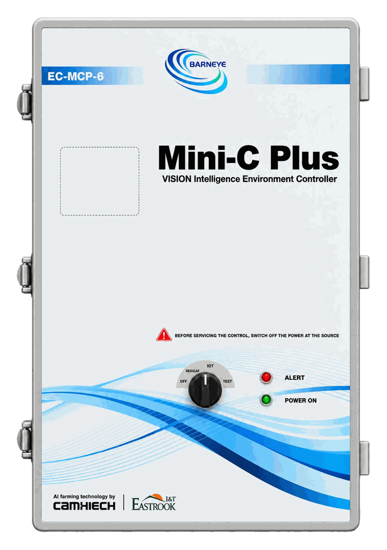
Mini-C Plus Vision Environment Controller

Vision, climate and equipment control on one modular platform — around ten camera streams processed on board, six module slots out, and a CAN module to reach the rest of the barn.

Available now

P/N ECU-01-006-000 ships today. Every figure on this page is a published specification of the released unit.

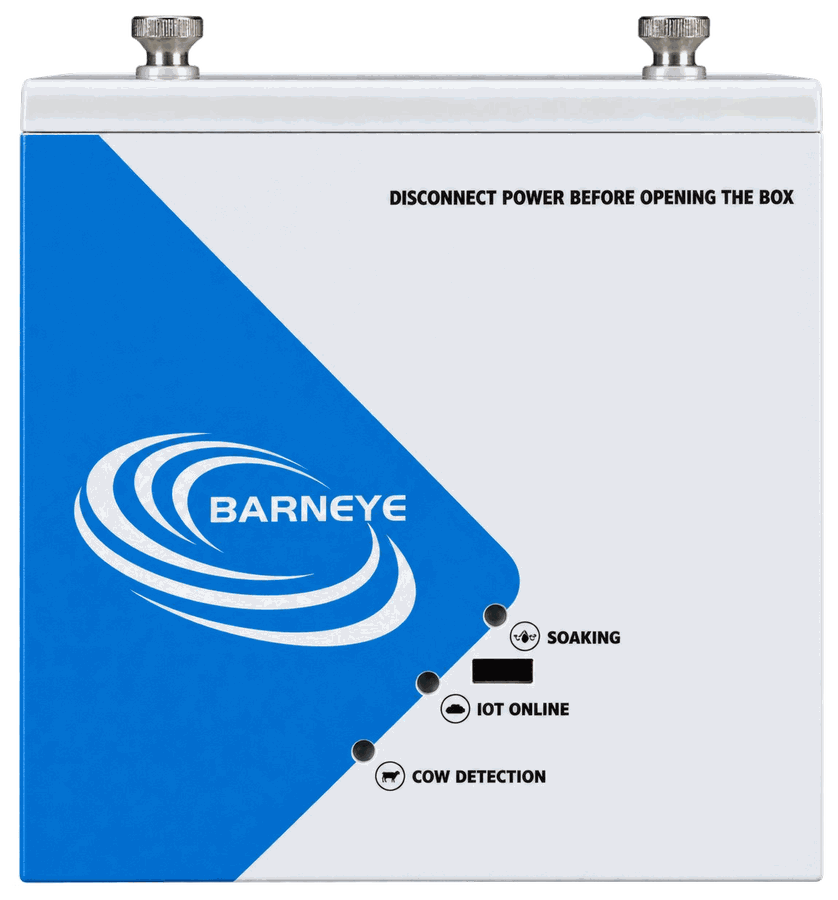
Photo for reference only. The actual product may vary.
Overview

See the cows. Sense the barn.

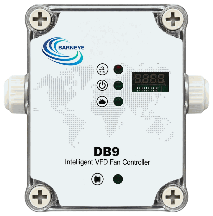
The Mini-C Plus is the computing unit the rest of the system reports to. Cameras tell it where the cows are, its own sensors tell it what the air is doing, and what it decides leaves over CAN to the DB devices on the barn wall — or through the modules fitted inside it.

  • Around 10 camera streams, processed on board — camera power and networking are provided by the site
  • Built-in temperature and humidity sensing with automatic THI
  • Six module slots for control, sensing and communication modules
  • A CAN module with two lines for multiple CAN-connected BARNEYE DB devices
  • 10Camera streams
  • 6Module slots
  • 2CAN lines via module
  • IP66Enclosure protection
Advantages

Why the Mini-C Plus is specified

Four capabilities that decide what the rest of the system is able to do.

Camera coverage by zone

Presence and location zone by zone, so equipment can be guided by where the cows actually are rather than by a barn-wide average.

Climate built in

Temperature and humidity are measured on board and turned into THI without an extra sensor node.

Modular by design

Six slots let a barn take only the functions it needs — variable speed, cooling, curtains, sensor inputs or communication.

Barn-wide connectivity

The CAN communication module carries commands out to multiple DB devices and brings their status back — it is a slot, not a fixed port, so a barn can also run without it.

Operation

See, sense, act

One loop, running continuously, over the whole barn.

  1. 01 See Cameras report cow presence and location, zone by zone.
  2. 02 Sense On-board sensors and fitted modules report climate, air quality and utilities.
  3. 03 Act Installed modules or CAN-connected DB devices run fans, cooling and curtains.
Configuration

Two ways to control the barn

Fit modules locally, run CAN devices across the barn, or combine both.

  1. CAN devices Use BARNEYE DB devices across the barn — one terminal per fan, soaker or inlet.
  2. Installed modules Fit control modules for direct equipment operation, or combine both routes on one controller.
  3. Both at once The two approaches are not exclusive: modules handle what is wired locally, CAN handles the rest.
Key specifications

Key specifications

ParameterSpecification
P/NECU-01-006-000
Position in the seriesVision with modular on-site control
Vision processingAround 10 camera streams, depending on algorithm, resolution and frame rate²
Camera connectionThrough the site network — camera power and PoE supply are specified for the installation
PoENot built in — an on-site PoE switch is added as the installation requires
Computing capacity expansionSupported
Memory4 GB RAM · 32 GB eMMC, expandable
Module slots6 card slots, 2.54 2×8 16-pin
Input voltage48–52 V DC
Input current1.5 A max., reverse-polarity protected
Network3 × Ethernet, 802.3/3u/3x/3az
Fieldbus and I/O1 × RS485 Modbus · 2 × USB 3.0
Mode switch4 positions — IoT, local, test, off
ProtectionIP66
Dimensions600 × 400 × 220 mm (L × W × H)
Operating range−20 to 60 °C, 10–90 % RH, no condensation
Storage range−40 to 105 °C, 10–90 % RH, no condensation
Modules

Expansion modules

Six modules share the slots on the Mini-C Plus — fit only the ones the barn needs.

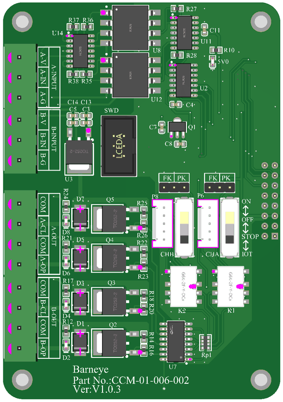
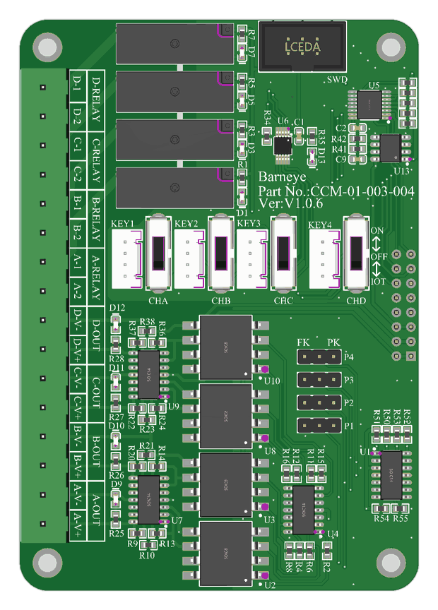
VFD Control Module
Drive and switch

VFD Control Module

CCM-01-003-004

The MD-VFD-4 is equipped with four 0–10 V DC outputs that command variable-frequency drives, plus a switch/enable signal for each channel. A manual override on the module lets an operator set the output by hand, without the network.

  • 4 × 0–10 V outputs
  • Speed signal, not power
  • Switch / enable per channel
  • Manual override
Inlet Control Module
Drive and switch

Inlet Control Module

CCM-01-006-002

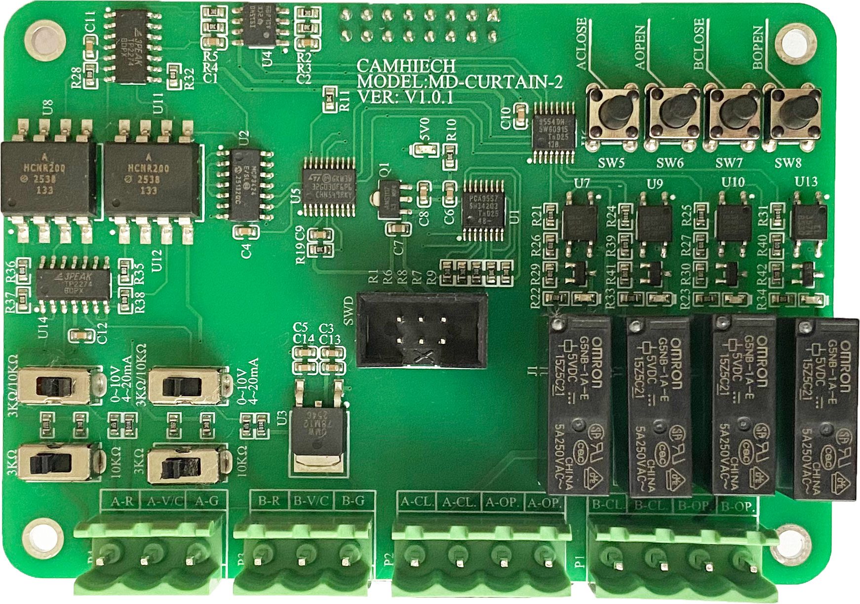
Integrates automatic control, position feedback and a manual override. One module switches and positions the inlets of a barn — side curtains, ventilation windows and chimney caps — with stable and reliable performance and simple operation.

  • Switch + position signal
  • Position feedback
  • Curtains · windows · caps
  • Manual override
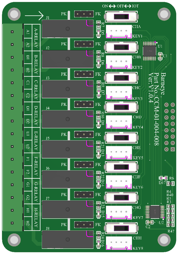
Switch Output Module
Drive and switch

Switch Output Module

CCM-01-004-008

The MD-SWITCH-8 is equipped with eight relay outputs that switch fans, heaters, lights and other equipment on and off. Each relay is a switch signal — the load power is supplied separately. A manual override on the module lets an operator trip each relay by hand, without the network.

  • 8 relay outputs
  • Switch / enable signal
  • For control cabinets
  • Manual override
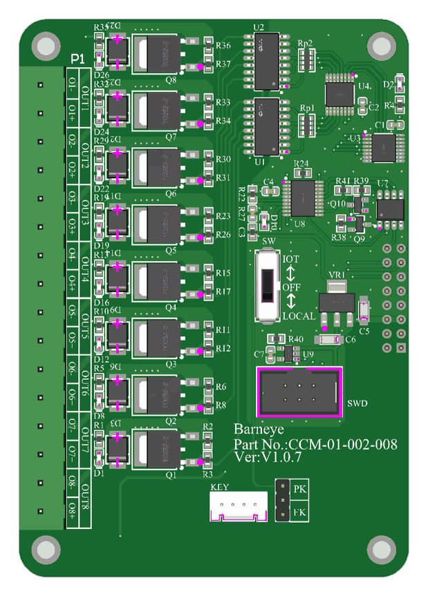
Vision Soaker Output Module
Valves

Vision Soaker Output Module

CCM-01-002-008

The MD-VSO-8 features eight 24 V outputs that drive the valves in the soaking system directly, across a wide input voltage range of 12 V to 36 V. A manual override on the module lets an operator drive the outputs by hand, without the network.

  • 8 valve outputs
  • 24 V drive outputs
  • 12–36 V input range
  • Manual override
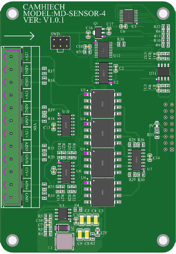
Sensor Input Module
Sense and connect

Sensor Input Module

CCM-01-005-004

The MD-SENSOR-4 is a four-input smart module that precisely measures analogue sensors.

  • 4 analogue inputs
  • Smart module
  • Precise measurement
CAN Communication Module
Sense and connect

CAN Communication Module

CCM-01-001-002

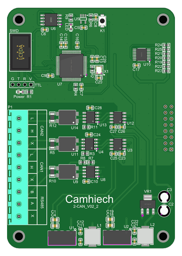
The MD-CAN-2 has two CAN interfaces. It connects multiple control units via CAN-H and CAN-L and delivers excellent compatibility and anti-interference performance.

  • Two CAN interfaces
  • Excellent anti-interference
  • Multi-unit linking
Slot rules. A maximum of six modules can be fitted, and the CAN communication module must sit in position 1. Power the unit down before changing a module, and leave at least 30 cm of clearance around the enclosure for heat dissipation.
Manual override. The four output modules — valve, inlet, switch and VFD — each carry a manual override on the module itself, so an operator can drive the outputs by hand without the network. The sensor and CAN modules read or connect only, so they have nothing to override.
Series

The rest of the series

One platform, three grades. The Plus is the one that ships today.

Sizing a controller for a barn?

Tell us the camera positions, the zones you want to control and the equipment already on the wall. We will come back with the slot plan and the CAN layout.

Ask an engineer
Datasheet and wiring diagram
Mounting and coverage plan
Spares and service intervals